Audio Cable Shield Connections
Shielded Enclosures
The designated shield contact and the shell of the equipment connector shall have a direct-current connection to the shielding enclosure via the lowest impedance path possible. This connection should be to the outside of the enclosure shield. It should have the lowest practical RF impedance (generally achieved with a short, wide conductor).
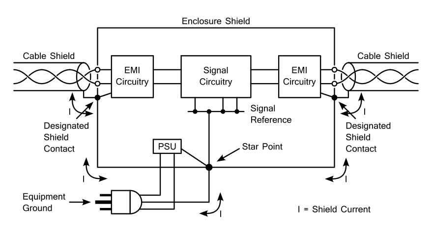
Figure 1: Connections with a Shielded Enclosure
EMI rejection circuitry should return EMI currents to the interface shield connection point with the lowest practicle impedance.
You should locate the 'Star Point', the connectors, and the signal circuitry as close as possible to each other in order to gain the greatest benefit from the cable shielding.
EMI filtering circuitry shown is optional and application dependant.
Unshielded Connectors
One type of unshielded connector is a terminal strip.
Cable-mounted connectors should be located outside the enclosure shield. The smallest practical opening in the shield should be made in order to allow them to connect to the equipment connector. Maximize the spacing between openings, which minimizes the path for EMI energy into or out of the enclosure. When possible, each connector should have its own opening.
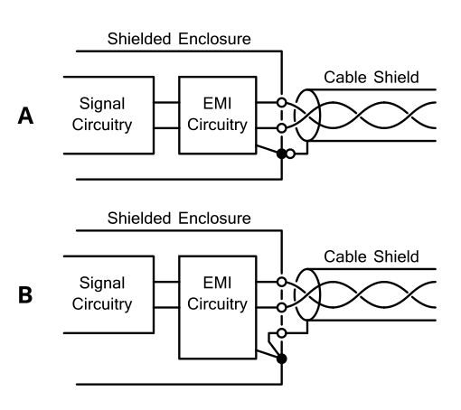
Figure 2: Unshielded Connectors with a Shielded Enclosure
Figure 2A is the ideal case, where the cable shield connects directly the the enclsoure sheild on the outside. If this isn't possible, like with an XLR connector, refer to Figure 2B. Here, the connection between cable shield and enclosure shield is as direct and low impedance as possible.
EMI rejection circuitry should return EMI currents to the interface shield connection point through as low an impedance as possible.
Three common problems with unshielded connectors:
- Since the connectors are unshielded, signal conductors can both recieve and radiate electromagnetic interferance.
- It's common for the connection from the cable shield to the enclosure to be relatively long, and for the shields of several lines to be joined together before connecting to the enclosure. This allows noise on the connection to radiate inside the equipment, with the connection acting as an antenna.
- It's common for the connection between the cable shield and the enclosure to pass through an opening in the enclosure shield. This opening provides a path for interferance to enter or exit the enclosure.
The shield terminal has commonly been identified as "G" in older equipment designs.
Unshielded Enclosures
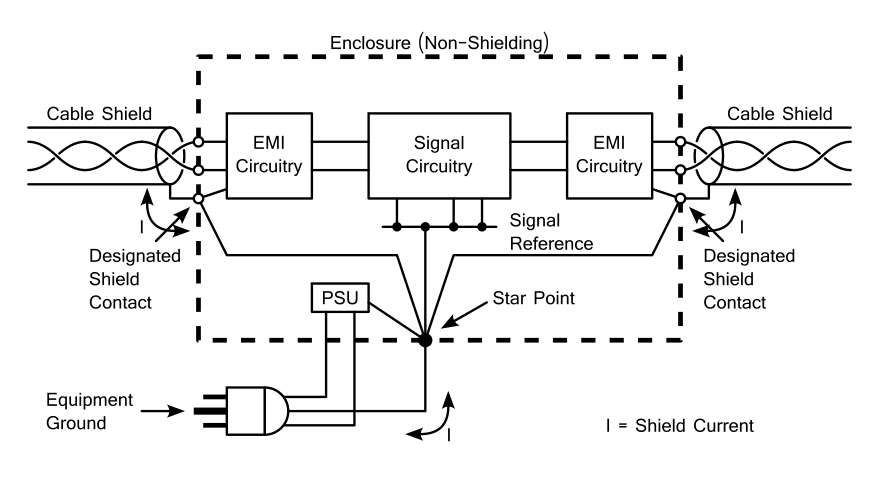
Figure 3: Connections with an Unshielded Enclosure
When the enclosure is unshielded, each designated shield contact and each connector should have a DC connection to the star point through a minimized impedance.
EMI rejection circuitry should return RF currents to the interface shield connection point.
Shield Interruptions
Sometimes a cable shield is disconnected (i.e. to remove ground loop noise). If this is done, it should be outside the enclosure shield. It should also only be at the receiving end of the cable (see Whitlock 1995).
Problem Examples
Here's some examples of common problems.
Example 1
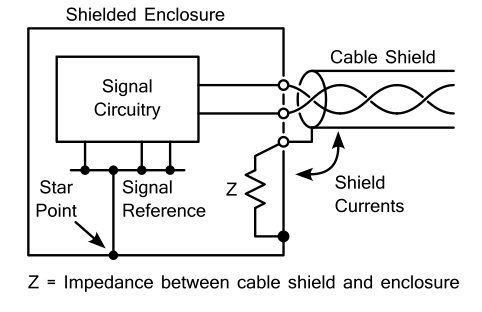
Figure 4: Effect of the Impedance of the Connection Between Cable and Enclosure Shields
Common mode voltage increases linearly with increasing impedance between the cable shield and the enclosure (Z). The impedance of the connection between the cable shield and the enclosure should be minimized.
When the connection is inside the enclosure, it behaves like an antenna and couples RF energy into the enclosure. Minimize the coupling by making the connection as short and wide as possible.
Example 2
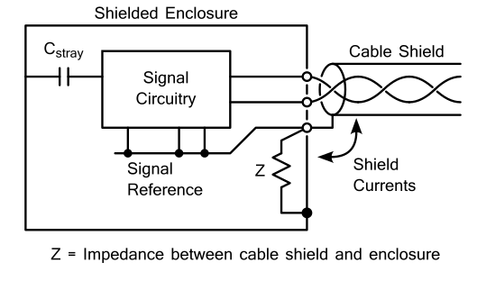
Figure 5: Common Impedance Coupling 1
The connection of the signal reference to the connector shield contact instead of directly to the enclosure at the star point makes the impedance from the impedance form the cable shield to the enclosure a common impedance between the cable shield current and the signal circuitry. Stray capacitance between signal circuitry and the enclosure completes the current loop.
Normally current isn't supposed to flow from the signal circuitry to the enclosure (its connection is a voltage reference, not a current return), but the stray capacitance forms a loop it can flow around.
Example 3
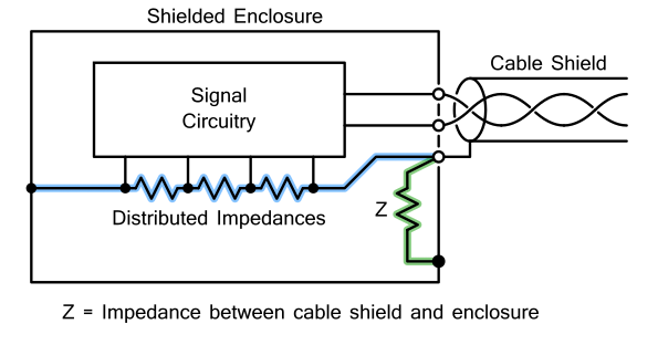
Figure 6: Common Impedance Coupling 2
Here, cable shield current gets to the enclosure through two different paths (highlighted blue and green). Path 1 (green) is from the cable shield to the enclosure through the pin 1 connection. Path 2 (blue) is through the signal reference and it's connection to the star point. Common impedance coupling occours in both these paths. The impedance of each section of these paths changes based on its geometry.
The voltages induced by the cable shield currents flowing through these path impedances will be coupled into the signal circuitry.
Example 4
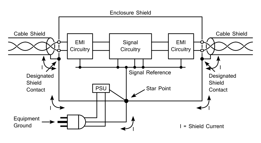
Figure 7: EMI Circuitry Grounded to Signal Reference
Make sure that EMI Filter Circuitry is grounded directly to the enclosure. It shouldn't be connected directly to the signal circuitry ground.
Sources
- AES48-2019: AES standard on interconnections - Grounding and EMC practices - Shields of connectors in audio equipment containing active circuitry (link)
- Rane, RaneNote 110: Sound System Interconnection (written 1985, last revised 11/15) (link)
- B. Whitlock "Balanced Lines in Audio Systems: Fact, Fiction, and Transformers", J. Audio Eng. Soc., June 1995, vol. 43, pp. 454-464 (1995 June) (link)